|Articles|September 6, 2022
Bilateral Small Incision Lenticule Extraction with SMILE pro using the VISUMAX 800
Advertisement
Introduction
Since its introduction in 2011,1 small incision lenticule extraction with SMILE using the VisuMax femtosecond laser (Carl Zeiss Meditec, Jena, Germany) has become a well renowned procedure, with over 6 million surgeries performed by more than 2,500 surgeons globally. The VISUMAX 800 femtosecond laser (Carl Zeiss Meditec, Jena, Germany) was released in 2021 as the successor of the VisuMax with the aim of improving practicality, compatibility, the patient experience, the user experience, as well as clinical outcomes.
Case Report
On the 24th August 2021, a 34-year-old woman presented for a corneal laser refractive surgery assessment at the London Vision Clinic, London, United Kingdom, after experiencing frustration and discomfort from her contact lenses. On examination, the patient had uncorrected distance visual acuity (UDVA) of 20/100 in the right eye, with a manifest refraction of -2.00 -3.00 x 126 (20/16-2), and 20/50 in the left eye, with a manifest refraction of -0.75 -2.75 x 126 (20/16+1). Central corneal thickness was 572 µm in the right eye and 568 µm in the left eye. Slit lamp and dilated fundus examination were unremarkable in both eyes. Corneal topography, tomography, epithelial thickness profile, and aberrometry were within normal limits for an eye with high astigmatism, so the patient was deemed suitable for corneal laser refractive surgery.
The patient was scheduled for bilateral sequential SMILE with the VISUMAX 800 with an experienced surgeon (DZR) on the 22nd of September. The target refraction was +0.27 dioptres (D) in both eyes based on our protocol algorithm targeting hyperopia based on age in accommodating patients. Lenticule and incision programming was according to the Standard Protocol2 with an intended cap thickness was 135 µm, the cap diameter was 8.0 mm, and the optical zone was 7.0 mm with a 0.10 mm transition zone. A primary 2.0 mm superotemporal small incision and a reserve superonasal 2.0 mm small incision was created in both eyes.
For the afternoon surgery list, our technicians rearranged the operating theatre shifting the cataract surgery setup from the morning (ARTEVO®, Centurion™) for SMILE in the afternoon (Figure 1). The VISUMAX 800 was rolled from a corner of the operating room, where it is stored when not in use, to the centre of the room next to the surgical bed used for both intraocular and corneal refractive surgery. The VISUMAX 800 possesses a design of two fully retractable arms, a laser delivery arm for femtosecond cutting, and a second arm with a high quality ZEISS surgical microscope. When these arms are left in the vertical position, the laser controls a small footprint, and therefore can be tucked away at the side of the room.
Once the operating theatre was prepared, the nurses brought the patient into the room and guided her to the operating theatre slit lamp. Here, I placed 3 corneal markings on the horizontal and vertical planes to use for referencing the cyclotorsion overlay tool during treatment. The patient was then assisted onto the surgical bed. With the laser arms in the upright position, there is unimpeded access to the bed, providing an open sky experience for the patient, compared to other systems where the device creates an enclosure over the patient.
After proceeding with our standard operating data entry checks, I began the treatment session by pressing the button to lower the laser delivery arm to the horizontal position above the patient.shows the whole case. The side and top view cameras include an overlay of the resting position of the laser arm to guide my adjustment of the height of the laser before lowering the arm. With the laser arm in position, the laser began recording the internal video, along with side view, top view, and room audio. The contact glass was attached to the treatment cone, and the system calibrates for the individual contact glass geometry. The right eye was taped shut, anesthetic drops were applied and the speculum was inserted on the left eye, the eye to be treated first.
Video 1
l began by slowly lowering the laser delivery arm towards the eye by gently rotating the joystick while under video visual control. This patient-centered design means that the patient remains static through the procedure, which from my observation produces a much more relaxed experience than when the patient is moved on the bed towards the contact glass under an enclosed space. During docking, the new CentraLign® assistant function produces an overlay depicting the vector difference between the corneal vertex and the current position of the treatment cone (Figure 2 and Video 2).
Video 2
The overlay consists of a cross-hair reticle with a 0.2-mm diameter circle at the center of the contact glass. As the eye approaches the contact glass, the pupil edge is automatically identified and displayed as a blue dotted line. The location of the corneal vertex is calculated relative to the pupil center according to the data entered in advance from the topography scan. The corneal vertex is indicated by a small circle, which is connected by a straight line to the center of the contact glass (i.e. the treatment center). This “lollipop” overlay is initially coloured yellow. Minor horizontal adjustments are made using the joystick to align the corneal vertex with the treatment center. The lollipop changes to green once the corneal vertex is within 0.2 mm of the treatment center.
Once satisfied with the centration, I initiated suction to immobilise the eye at very low vacuum (50 mmHg) which the patient does not even perceive as having started. At this point, the software displayed the Oculign® cyclotorsion screen that shows a reticle guideline overlay representing the horizontal axis of the contact glass (Figure 3 and Video 3). I used the joystick to rotate the reticle guidelines to be aligned with the corneal marks for perfect cyclotorsion control.
I pressed the foot pedal to begin the femtosecond cutting. The laser head and delivery optics are essentially identical as in the VisuMax. The main difference is that the VISUMAX 800 possesses ultra-high-speed deflecting mirrors enabling the laser head to operate at a pulse frequency of 2 MHz compared to 500 kHz, meaning that the femtosecond cutting for this SMILE pro procedure was 10 seconds compared to what would have been about 30 seconds with the VisuMax. Once complete, the suction is automatically released and the laser delivery arm automatically raised 3 cm away from the patient. One button push leads to the swapping of the laser delivery arm to the vertical position and the surgical microscope to lower to the horizontal position in focus with the eye.
Video 3
The lenticule dissection and extraction technique was performed using the Standard Technique as described previously.2 Once extracted, the lenticule was distended on top of the cornea and, as dictated by the Standard Technique, was inspected for completeness using the built-in slit projecting illumination in the presence of fluorescein dye under cobalt blue illumination. Moxifloxacin and Tobramycin/Dexamethasone eye drops were instilled as prophylaxis, and the procedure was repeated on the right eye. The total treatment time for both eyes is 9 minutes.
Once the surgery was complete in both eyes, the nurse assisted the patient to the operating theatre slit lamp for examination. Fluorescein dye was instilled, and using a dry micro-spear, the redundant portions of the cap were distributed to the periphery to avoid microfolds and delayed visual recovery. The patient was then instructed to use artificial tears every hour, as well as standard antibiotic and anti-inflammatory eye drops, and sent home to rest.
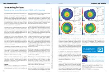
One month after surgery, the patient returned with no subjective complaints. The UDVA was 20/16 in both eyes, with a manifest refraction of +0.25 -0.50 x 23 in the right eye, and +0.50 -0.25 x 125 in the left eye. Corneal topography was as expected and showed a perfectly centred treatment in both eyes (Figure 4). Optical coherence tomography B-scan revealed no irregularities at the interface level in both eyes. All further ophthalmic examinations were unremarkable.
Discussion
The present case report has shown SMILE to be effective for treating high compound myopic astigmatism with the VISUMAX 800. Using the new CentraLign® and OcuLign® assistant functions, the VISUMAX 800 was able to effortlessly achieve essentially perfect centration (Figure 3). Currently, the CentraLign® function requires manual data entry of the x and y coordinates of the corneal vertex relative to the pupil border, as obtained by ATLAS topography (Carl Zeiss Meditec), and the OcuLign® function requires corneal markings at the slit lamp. However, both these features are soon to imported automatically from an iris registration image acquired before in a future update.
Additionally, the new Refractive Workplace (Carl Zeiss Meditec), is expected to be released shortly. This new treatment planning software is a plug in, based on FORUM patient data management (Carl Zeiss Meditec, Jena, Germany), which enables surgeons to plan the treatments such as SMILE pro remotely. It will be able to integrate measurements from diagnostic devices and treatment plans can be imported on the refractive laser devices. It is to be expected that surgeons will be able in the future to remotely plan laser refractive procedures such as SMILE pro using centration data from topography, thickness data from OCT tomography and iris registration data such as the IOLMaster 700. Automated data import will not only improve workflow efficiency but safeguard against the possibility of data errors currently requiring multiple layers of cross-checks. Overall, the VISUMAX 800 to me represents a true generational leap from the first generation lenticule extraction devices currently available.
REFERENCES
Sekundo W, Kunert KS, Blum M. Small incision corneal refractive surgery using the small incision lenticule extraction (SMILE) procedure for the correction of myopia and myopic astigmatism: results of a 6 month prospective study. Br J Ophthalmol. 2011;95:335-339.
Reinstein DZ, Archer TJ, Carp GI. The Surgeon’s Guide to Small Incision Lenticule Extraction (SMILE).Thorofare, New Jersey: SLACK Incorporated, 2018.
DISCLAIMER
en-INT_34_021_0074I Not all products, uses, treatment options and protocols referenced are officially approved in every market or supported by a product’s intended use in every market. Approved labeling and instructions may vary from one country to another. For country-specific product information, see the appropriate country website. Product specifications are subject to change in design and scope of delivery as a result of ongoing technical development. The statements of the author reflect only his personal opinions and experiences and do not necessarily reflect the opinion of any institution that he is affiliated with. The author alone is responsible for the content of his experience reported and any potential resulting infringements. Carl Zeiss Meditec AG and its affiliates do not have clinical evidence supporting the opinions and statements of the author nor accept any responsibility or liability of the authors’ content.
Dan Z Reinstein, MD is a consultant to and receives travel expenses from Carl Zeiss Meditec AG and has a financial interest in ArcScan Inc.
Advertisement
Related Content
Advertisement

Latest CME


Advertisement
Advertisement
Trending on Ophthalmology Times Europe
1
Hands-on training, real surgeon input: inside BVI's new Experience Hub
2
Saudi cohort study finds JIA drives most paediatric uveitis cases
3
How the ocular microbiome may shape outcomes in keratoplasty
4
Phaco-GSL outperforms in acute angle-closure glaucoma over chronic cases, 2-year study finds
5